TRANSFORMER
So far I’ve come up with a dozen “transformations”. Using the BRIDGE BEAMS from other structures I built:
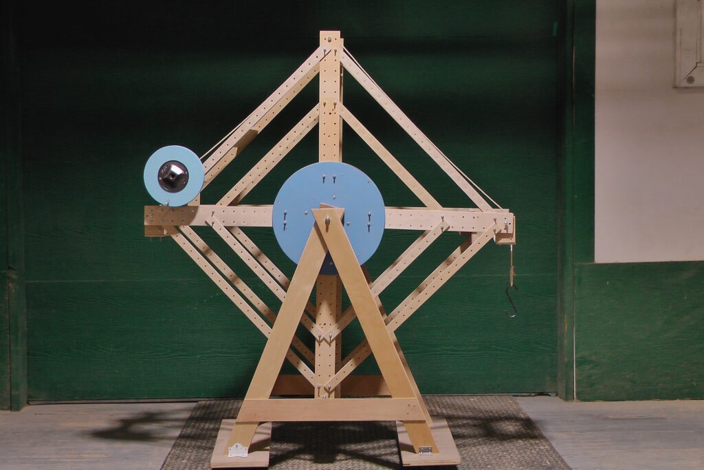
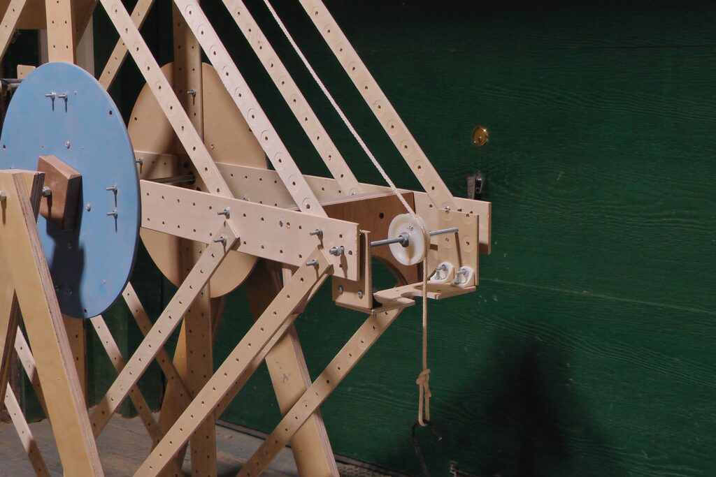
a ferris crane
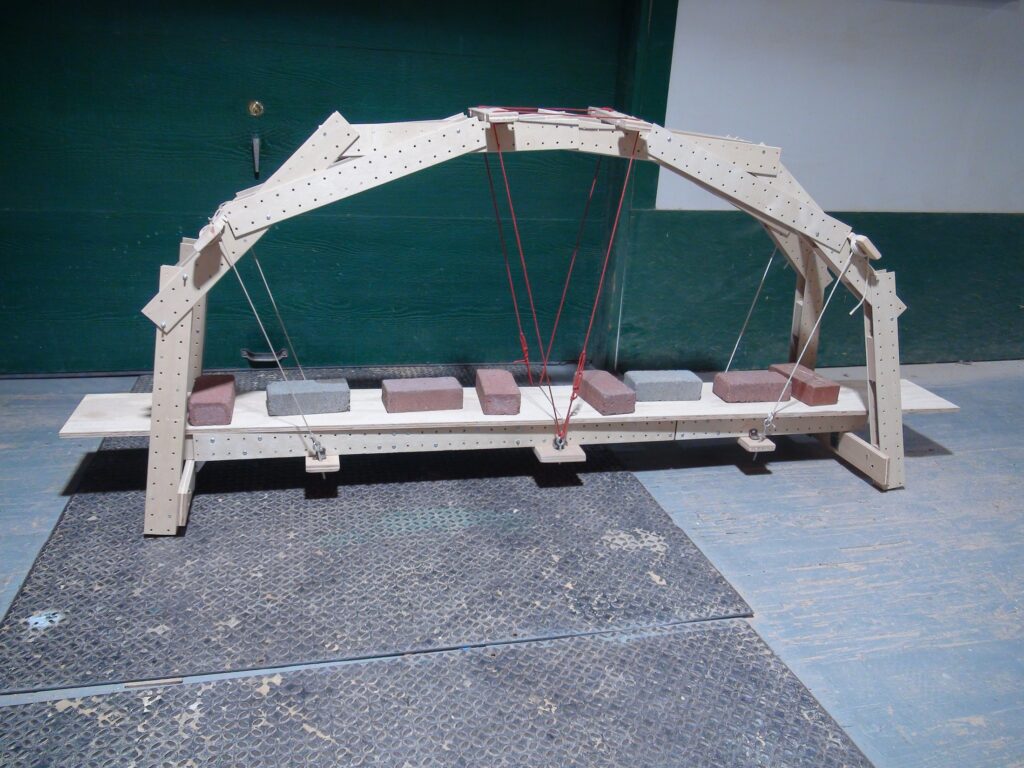
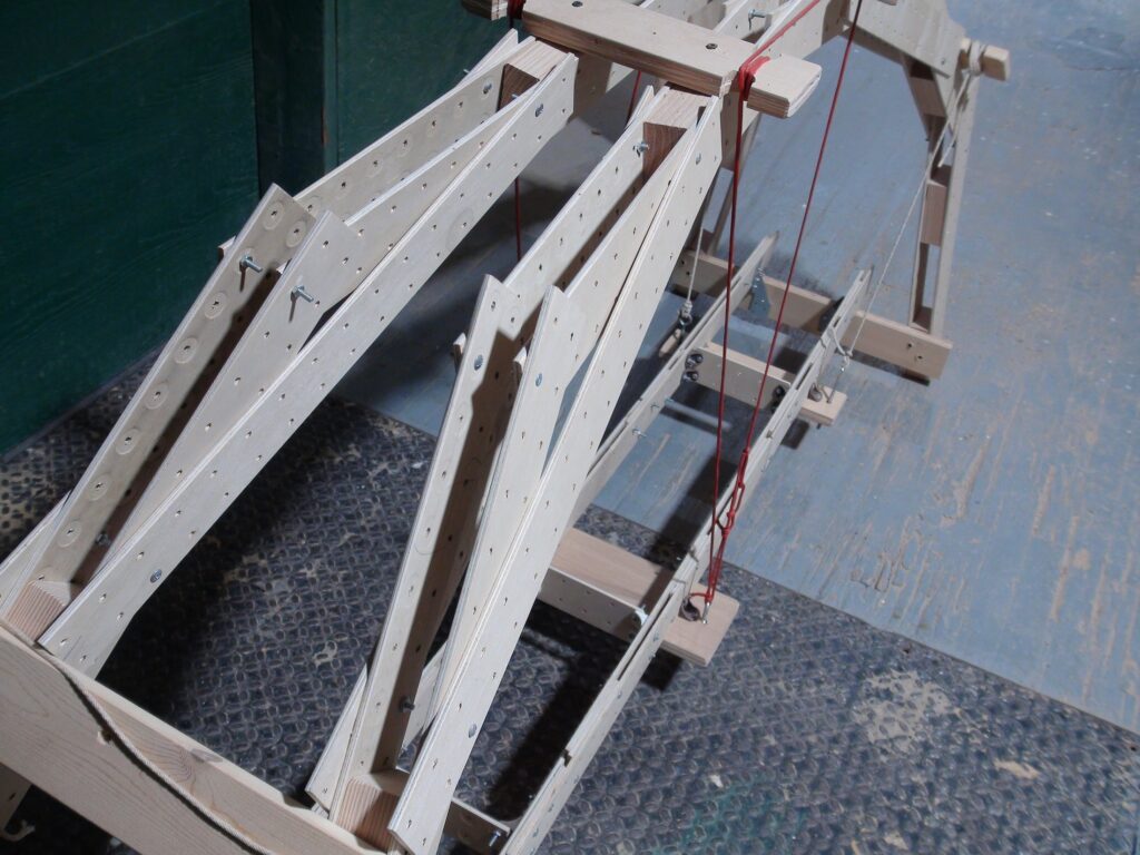
A 2 rib arch bridge
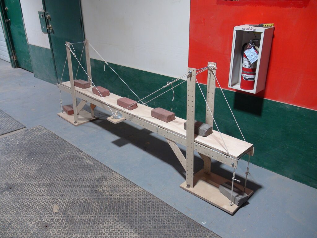
Next I built a cable-stayed bridge
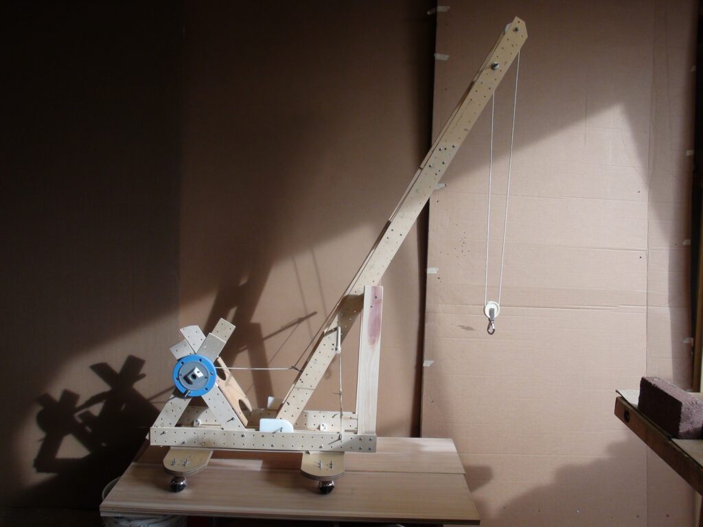
Here’s another crane- a little different than the normal models I’ve built.
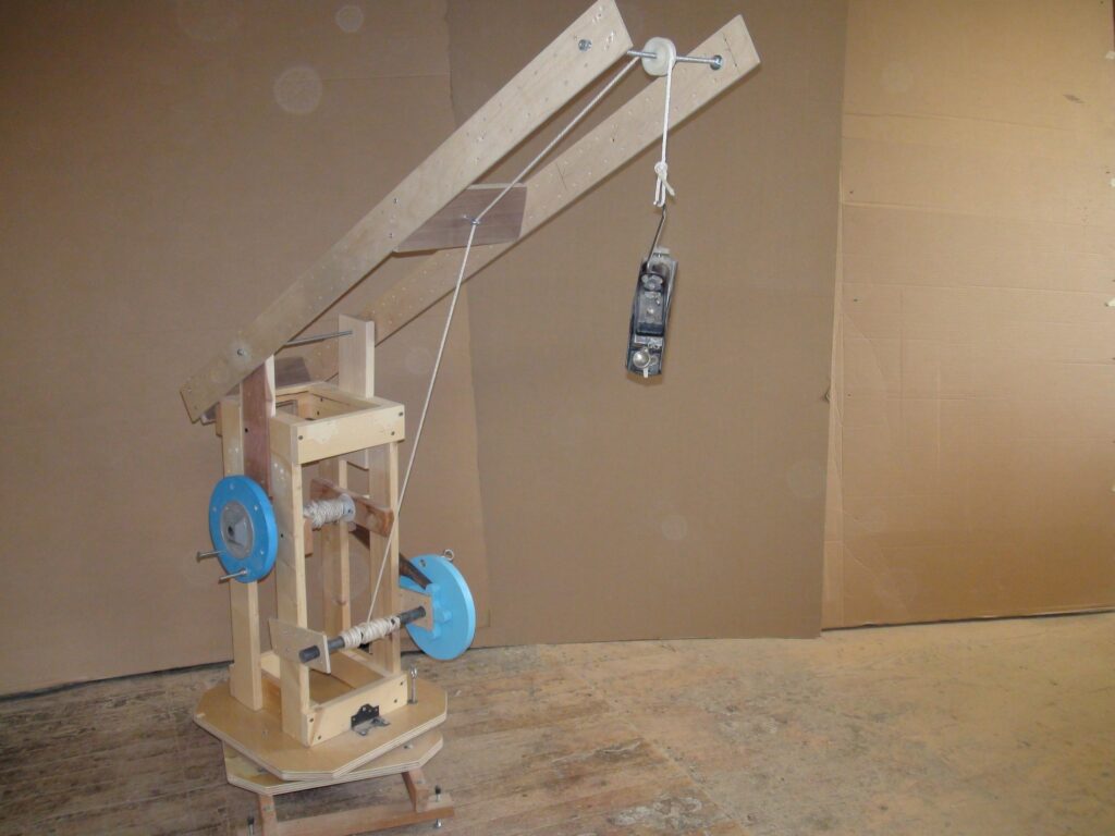
The load ( the small block plane) is controlled by the windlass- just like with all the other cranes. But the boom/jib pivots on a length of threaded rod and the back end of the jib is connected with a line to the 2nd windlass. watch the video.
how about an excavator
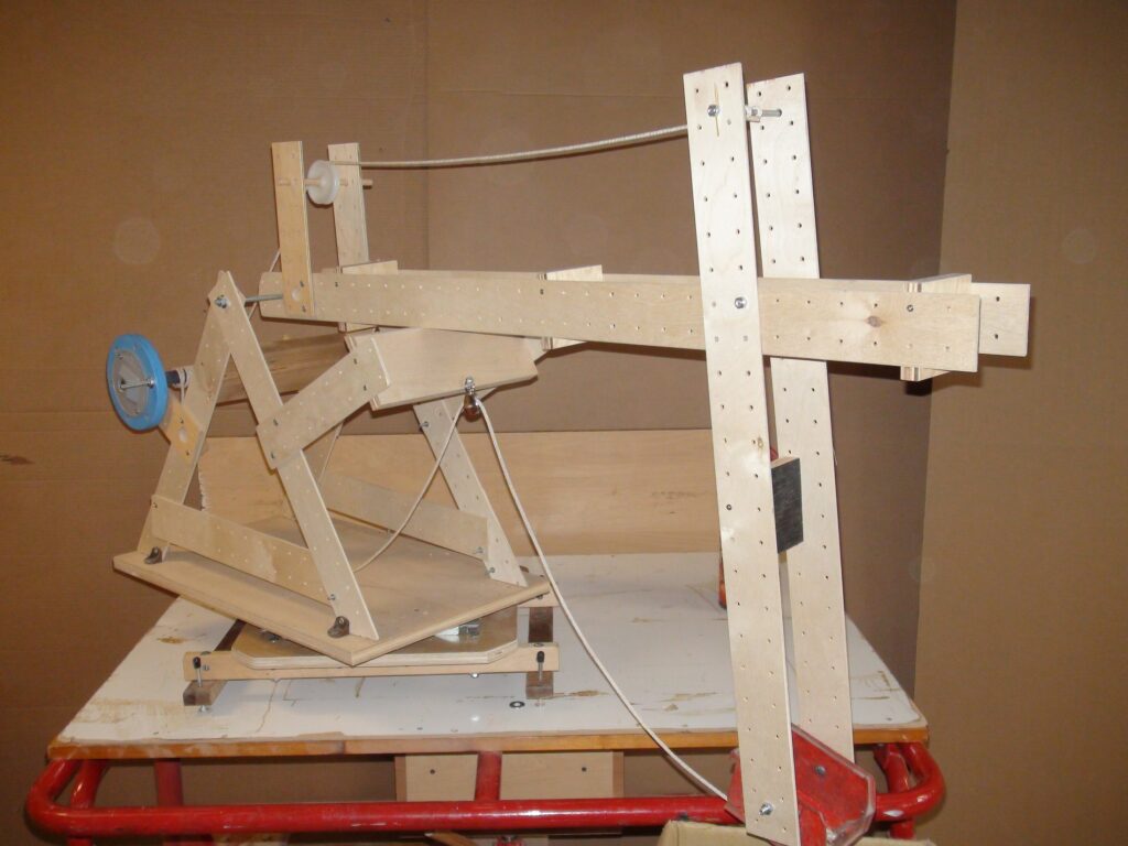
See it in action
I saw a picture of a simple crane on an Erector set web-site. Remember erector sets? look it up.
I changed it around a bit and came up with this.
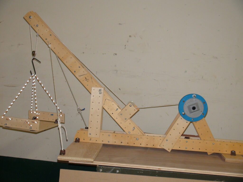
This is the 3 boom crane- the boom can be fixed at either 60 45 or 30 degrees and it
can be reconfigured to become a –
catapult
elevator
cable stayed bridge
high line
CATAPULT
I took the boom apart and used the 2 long members to build a tower braced to the crane base. The other 2 members from the boom are connected and hinged to the tower- the long side is 3 times the length of the short side, This means whatever is attached to the tip of the long side moves 3 times faster than something atached to the short side. That’s why I can fling the sheave (the pulley wheel) so easily.
Next was an elevator.
Again I kept the crane base and used the 4 members of the boom to build a tower. I put a sheave on top and 2 more sheaves to redirect the line (string) to the windlass. Finally I added a small cardboard box which hangs from the end of the line with a passenger (tape measure) inside and presto– an elevator.
Now comes a single tower cable-stayed bridge. The deck of the bridge is supported by the “stay” which runs over a sheave in the tower, over another sheave at the far end of the deck and then down to several C-clamps as counter-weight.
I change the angle to 20 degrees. Will that require more or less counter-weight.
A few years back I shot a video that explains this subject much better. I used a crane built with 1×4 lengths of spruce. I “ran” the numbers- computing the moment of the load and the crane body with the boom at different angles.
go to LIFT BRIDGE/CRANE
Hi-Line
What do you do when you’re building a bridge that spans a river or a deep gorge and there’s limited access to one side?? It’s easy for trucks to bring material to ,say the west side of the gorge, but there are few roads on the east side.
One option is a Hi-Line. You build a tower on each side of the gorge, make sure it’s well braced and then string a series of strong cables between the towers. Now you can hang a “trolley” from the cables.
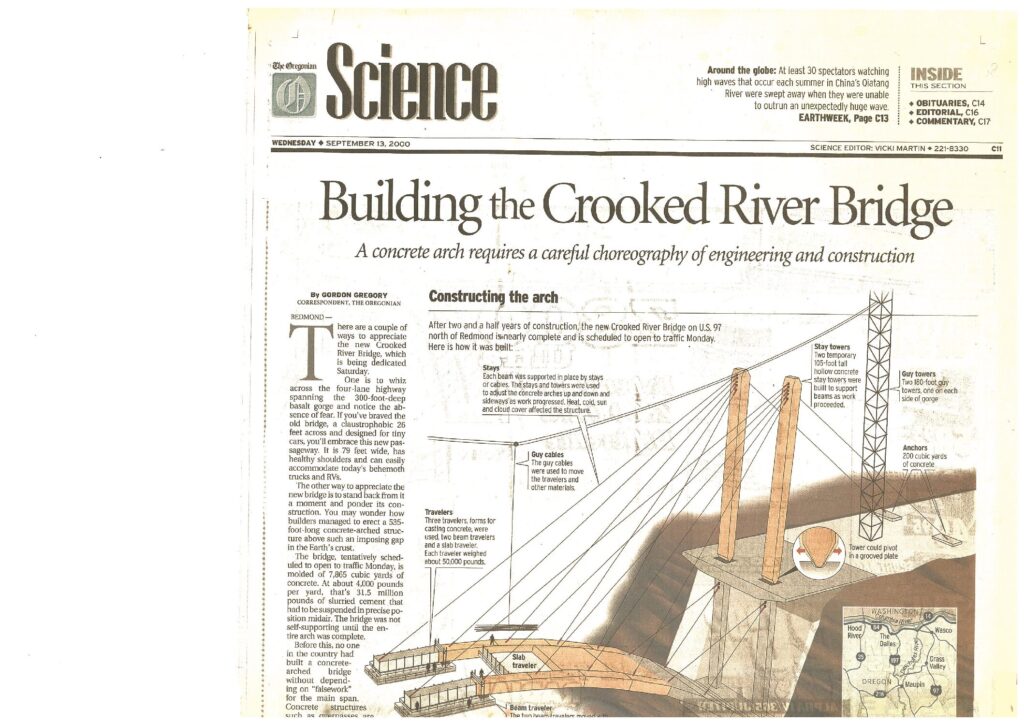
The new Crooked River Bridge is an arch bridge in Oregon. The arch is made up of a number of concrete segments. Starting from the cliff sides, they poured concrete 1 small section at a time, slowly working their way (from both sides simultaneously) towards the center. So how could they support these heavy sections? They ran cables from the temporary “stay towers” to the ever advancing arch members.
Now look at the “guy towers”. The guy cables supported a sort of trolley that was used to move material.
LUFFING IB TOWER CRANE can be re-configured as:
1-overhead crane- You see these overhead cranes in large factories where they have to move machinery and material around. There might be 2 large beams mounted to the walls or hung from the ceiling-and a lifting carriage would ride along tracks .
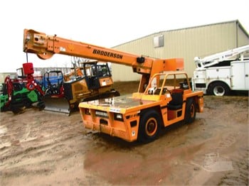
2-Next comes a pick and carry crane.
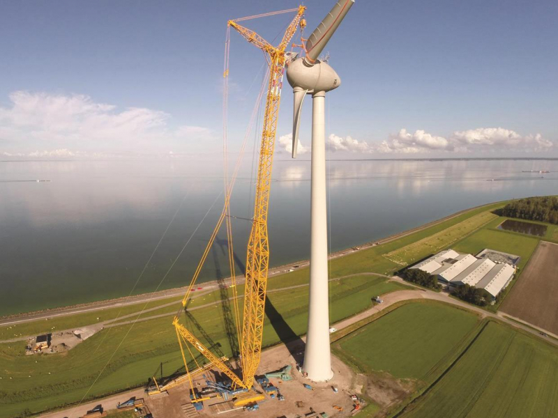
To install wind turbines taller and taller cranes have been developed.
3-So I decided to use the long (65″) jib/boom from the “luffer” to build this new model.
