CRANE/BRIDGE COMBO $1150
I thought I’d use a model of a cable stayed bridge to teach the kids about force vectors and trigonometry.
Place a load on the deck and have it supported by a thin string. then measure the angle of the string and compute how heavy a load it would take for the string to break and the load come crashing down.
Lots of variables for the students to consider- size and placement of the load, angle of the supporting cable, thickness of the wooden dowel.
In other words there are lots of engineering formulas for the kids to master. And then there’s assembling the crane/bridge model. That will take awhile.
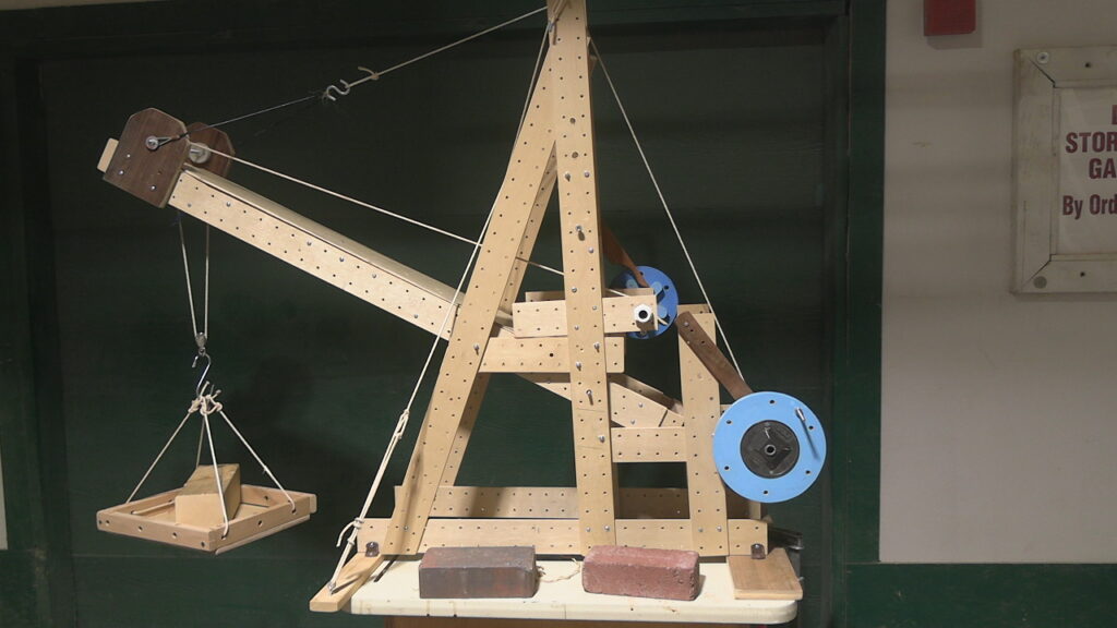
By adding just a few more members (pieces) we now have a working model crane.
I made some improvements to the crane.
-I added an extension to the boom(4ft long) making it 6 1/2′ long now
-I installed a heavy duty lazy susan- so now the crane can swivel (slew) a full 360deg
-in addition to the single sheave pulley connected to the hook, I added a double sheave pulley.
Now back to the main reason for designing this crane/bridge combo- computing the amount of tension in the support cable, and figuring out when/if the deck will fall.
The 2×4 sits on the ground-or rather 1 end sits on the ground and the other end is held up by a rope.
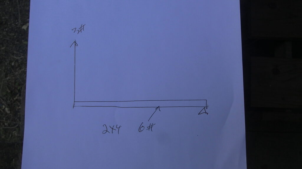
The 2×4 weighs 6#. One end is resting on the ground ( I use a small triangle to denote this )- so the ground is supporting half the 6# load. Ben only has to use 3# of force to lift the other end.
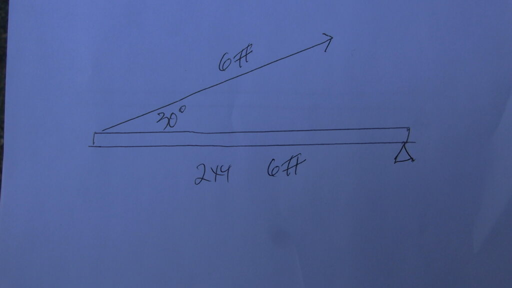
Now when Ben applies a force to raise the 2×4 at an angle of 30 degrees- he needs 6# of force. We have to find a way to be able to compute the necessary force in advance.
Easy- first we turn the forces into a right triangle.

The vertical leg is 3#- that represents the original force when the lifting angle was 90 degrees. The hypotenuse is the 6# force needed at 30 deg.
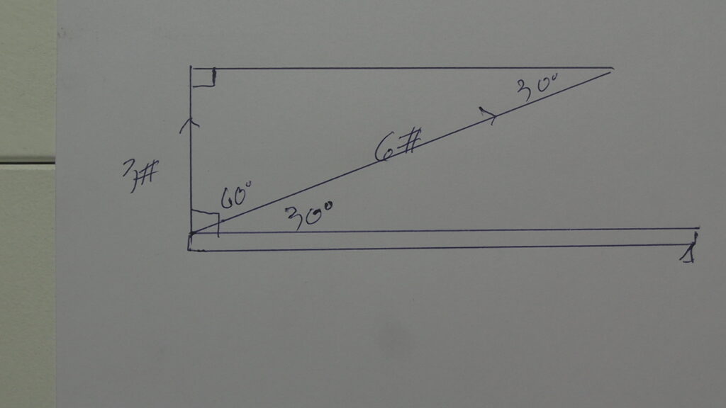
The complement to the 30 deg angle on the 2×4 is 60 deg. Which makes the upper angle 30 deg.
The ratio of the opposite side (opposite the upper 30 deg angle)–3#
over the hypotenuse – 6# is 3/6 or 1/2 or ,5
For those of you who don’t already know basic trig-this is SINE.— opposite divided by hypotenuse.
So we write it like this sine 30 deg = 3#/ 6#
sine 30 deg = .5
so substituting we get .5 = 3/6
Trigonometry shouldn’t be that confusing. Triangles only have 3 sides and 3 angles so how hard could it be.
So we can use trig to compute the Tension in the cable once we know the angle of the cable . With the cable at a 30deg angle the tension in the cable was 6#-.
Now let’s lower the angle to 20 deg.
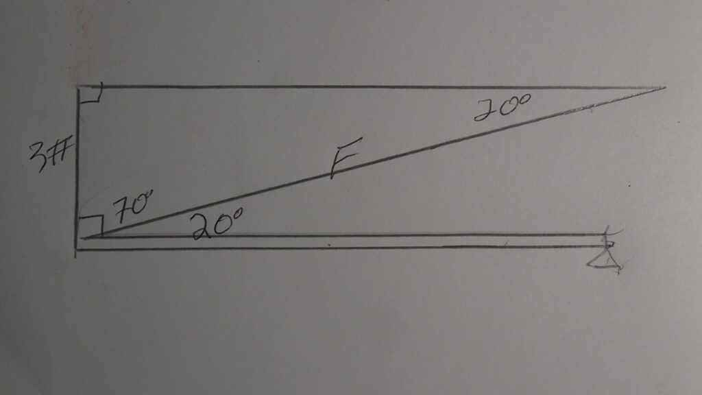
The vertical leg is still 3#, and F is the unknown FORCE needed to support the end of the 2×4.
Remember SINE is the opposite side (the 3# side) over the hypotenuse–(the value F)
so now we get sine 20 deg = 3#/F
sine 20 deg. = .342
and finally .342 = 3/F and solving for F we get 8.77 lbs. of force.
How much force would we need if the base angle was 10 deg? figure it out. all you need is the sine of 10 deg.
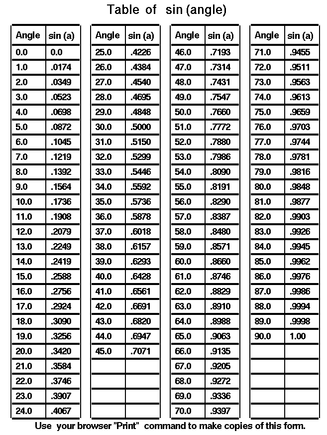
I encourage my students to forget using their calculators to find the trig values. Instead use the trig tables like the one below.
Here the kids can see how the sine values change as the angle changes/
1—–All this was for the 2×4, but we’re interested in the deck of the bridge, which weighs 4.4#s
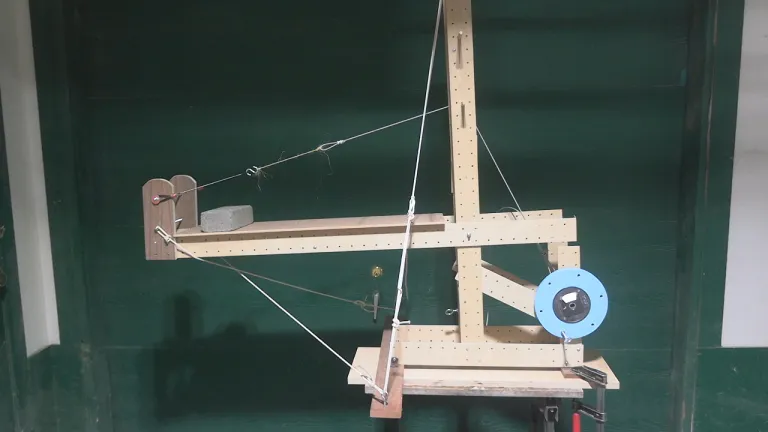
All these calculations are based on the fact the mass of the 2×4 is uniform throughout the length of the 2×4. To simplify our calculations we’re going to assume the same about the deck, even though you can see the end of the deck has the 2 brown plywood panels- making this end of the deck a little heavier than the other end.
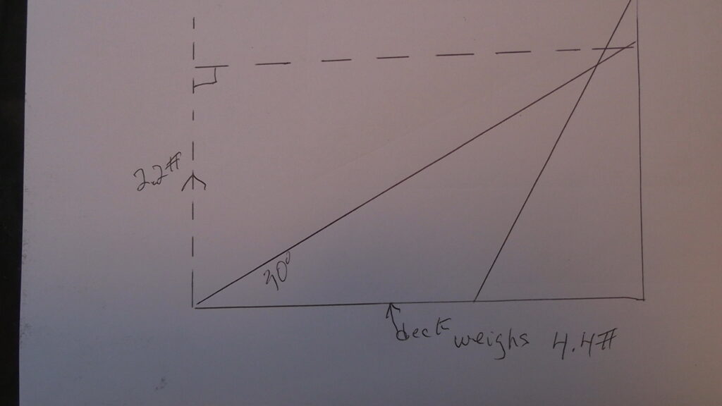
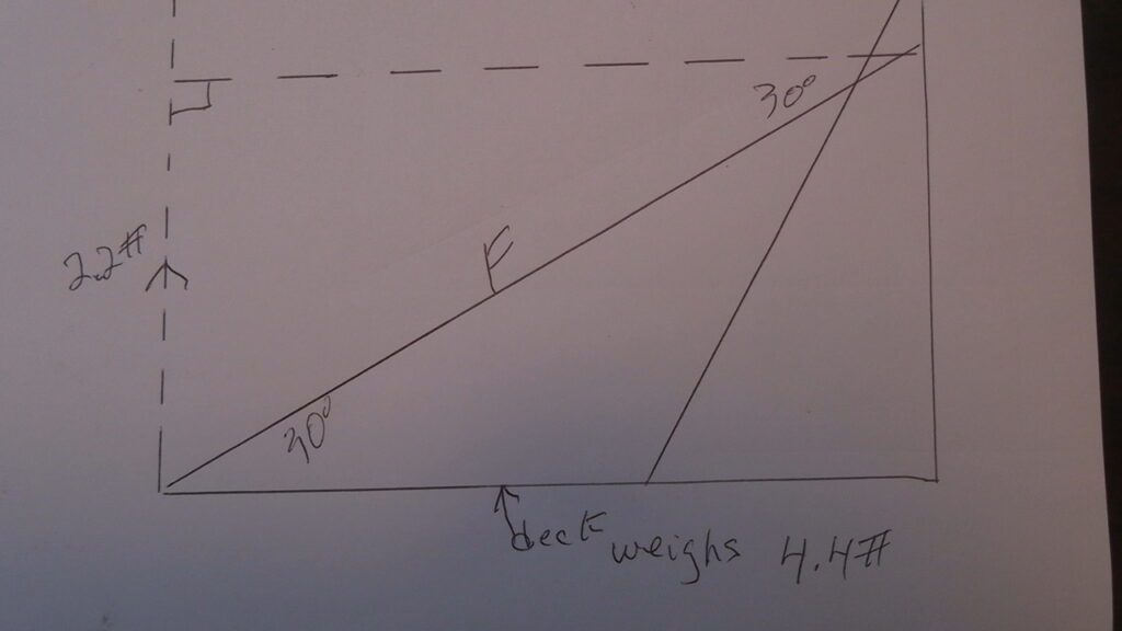
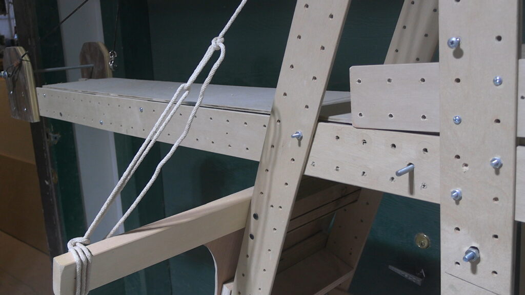
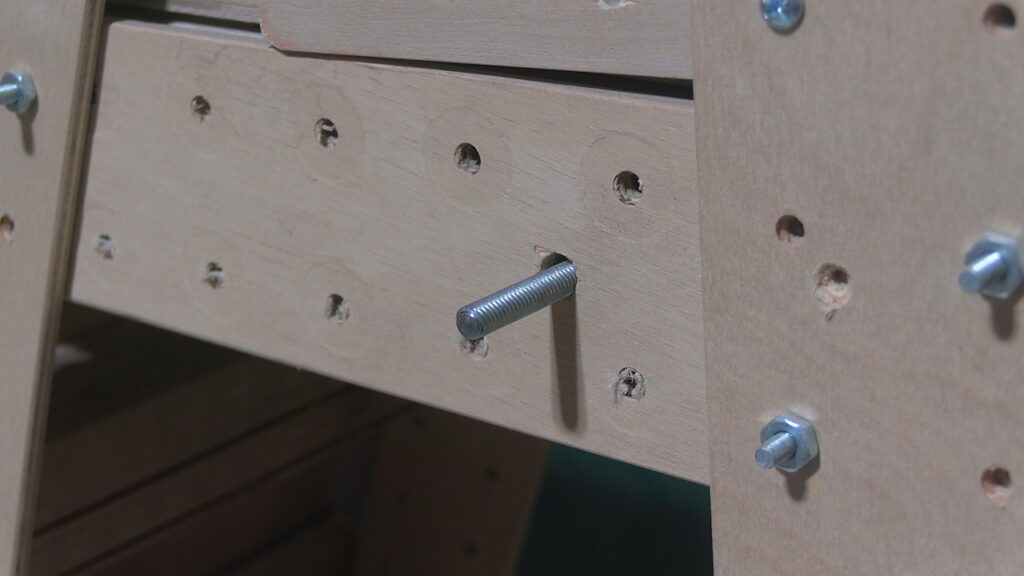
Here’s the set up for the deck —it weighs 4.4#s. Just as half the weight of the 2×4 was being held up by the floor, half the weight of the deck is supported y the steel pivot pin mounted in the tower. so the vertical part of the triangle is only 2.2 #s
Using the same SINE equation as before we get
sin 30 = 2.2#/ F
sin 30 = .5 so
.5 = 2.2#/F
F = 4.4#
That’s the force/ tension in the cable needed to support the deck. Now what about the brick?
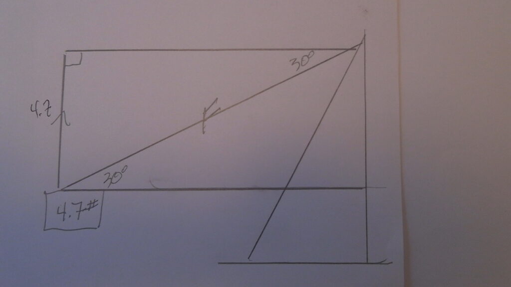
The entire 4.7# weight of the brick is being supported by the vertical leg of the triangle, so using the sine function we get;
sin 30 = 4.7 /F
sin 30 = .5
so .5 = 4.7/F and finally
F = 9.4#
Now the combined Force or tension in the cable is 9.4 + 4.4 = 13.8#s
The cable was strong enough to support this amount of Tension. Go back and look at the 1st video above.
In this 1st video the angle of the cable was 35 deg.
So here’s the formula: for half the weight of the deck -2.2#s, we get
sin 35 deg. = 2.2/F
sin 35 = .573
.573 =2.2/F
F = 3.83 #s
With a higher angle there’s less Tension in the cable.
Now to find the tension in the cable just for the 2 bricks. 2 bricks = 9.4#s
sin 35 deg = 9.4/F
sin 35 = .573
.573 = 9.4/F
F = 16.4 #s
So the combined Tension in the cable is 16.4 + 3.83 = 20.23#s seems like a lot but the cable didn’t break.
When we lowered the angle to 15 deg. the cable snapped. How much tension was in the cable?
Remember there was only 1 brick and the cable couldn’t even support that load
First just the tension in the cable caused by the weight (4.4#) of the deck.
sin 15 = 2.2/F
sin 15 deg = .258
.258 = 2.2/F
F = 2.2/.258
F = 8.52 #s A lot more Tension in the cable just to support the deck.
Now for a single brick. sin 15 = 4.7/F
.258 =4.7/F
F = 4.7/.258
F= 18.2#s
for a total tension in the cable of 26.72 more than the T @ 35 deg with 2 bricks
To re-cap –
When the deck was at a 35 deg angle, the combined force (with a 2 brick load) was 20.23 #s.
When the angle was 15 deg. the combined force with just 1 brick was 26.72- that’s why the fiber broke.
Next I changed things up a bit. Instead of having the “cable” break when the Tension was too great, I substituted a wood dowel for the steel shaft that supported the sheave.
So this introduces a second set of variables- instead of the “cable” breaking, the dowel might break. I started with a 1/4″ dowel, but that broke too easily, so we went to a 5/16′ dowel. Next would be a 3/8″ dowel