ARCH BRIDGES
Arch bridges have been around for thousands of years. The Romans perfected the semi-circular arch bridge.
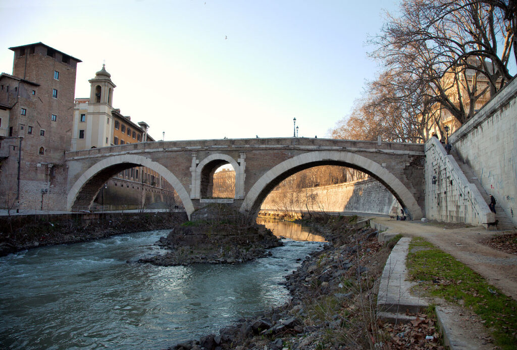
The Pons Fabricius was built in 62 BC.- still standing.
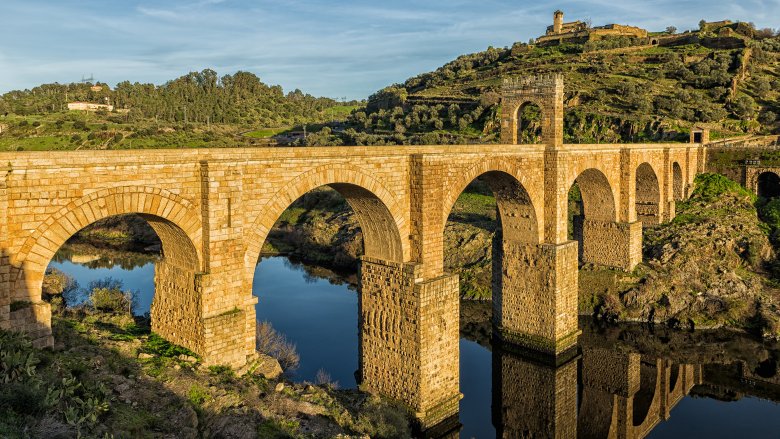
The Alcantara in Spain is also around 2000 years old.
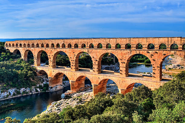
The Pont Du Gard is an aqueduct in France- used to carry water to a city.
So how do you construct an arch?
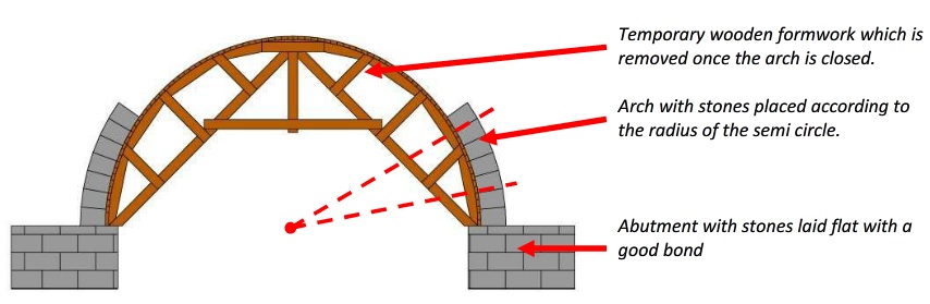
You start by building a wooden form ( semi-circular for the Roman arch), and lay the stones on top
Once the last stone – the Keystone is laid- the arch is complete and the wooden form (the centering) can be removed.
All the weight of the stones, and the live load ( the people cars etc.) presses down on the arch, compressing the stones.
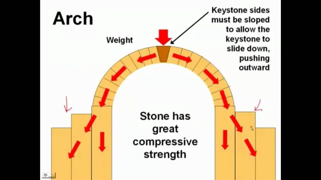
Stone is great for compression. But notice that as the line of this compressive force travels down through the arch, this force tends to spread the ends of the arch apart. There’s a vertical and horizontal component to the force. The vertical component does straight down into the ground- and as long the ground isn’t sand or mud- the ground will support this vertical force.
The horizontal force is another matter.
We got a little ahead of ourselves here—before we discuss a tied arch, let’s go over ABUTMENTS.
The Romans didn’t have high strength steel to tie their arches together- they used stone, scrap rock, dirt etc. to form abutments.

The stones on either side of the arch are heavy enough to contain the horizontal push.
Let’s take another look at the Pons (Latin for bridge) Fabricius.
So back to the abutment– where is the mass of stones Where the arch lands on the banks, you can see the heavy wall on one side and looks like a whole building, on the other.- these function as abutments. But where the 2 arches meet — it’s the island that serves as the abutment. All that rock and dirt are plenty heavy to counter-act the horizontal force of the arches.
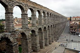
The aqueduct in Segovia Spain was supplying water to the town- from a water source 10 miles away- up until the mid 19th century.
Here’s what it might have looked like 2000 years ago .
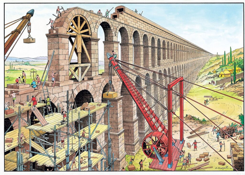
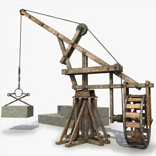
Now check out the cranes. The boom is made of 2 heavy wooden columns that join at the tip, and there’s a pair of pulleys with a mechanical advantage of 3 lifting the stone. Slaves were plentiful in those days, and you can see a couple of guys walking in the “squirrel cage” that’s connected to shaft where the line is wrapped. So for that windlass- say the radius of the “cage” is 6feet and the radius of the shaft/axle is 1 foot, we get a mechanical advantage of 6. Now we multiply that MA of 6 by the MA of 3 of the pulleys to get a combined MA of 18. There is of course a large amount of friction here- so the real MA might be half of that, but this was state of the art 2000 years ago.
Now on to tied arches.
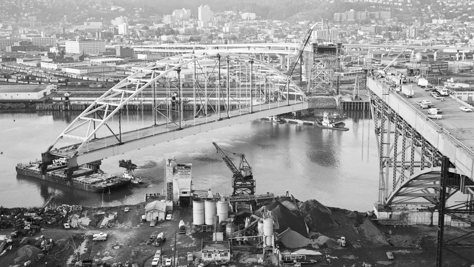
When they started the lift, the barges popped up as soon as the weight cleared the barges.
1-The sum of the forces in the vertical direction must all add up to zero and
2- the sum of the forces in the horizontal direction must also add up to zero.