TRUSS BRIDGES
What is a beam bridge, truss bridge and how can you compute the forces at play.
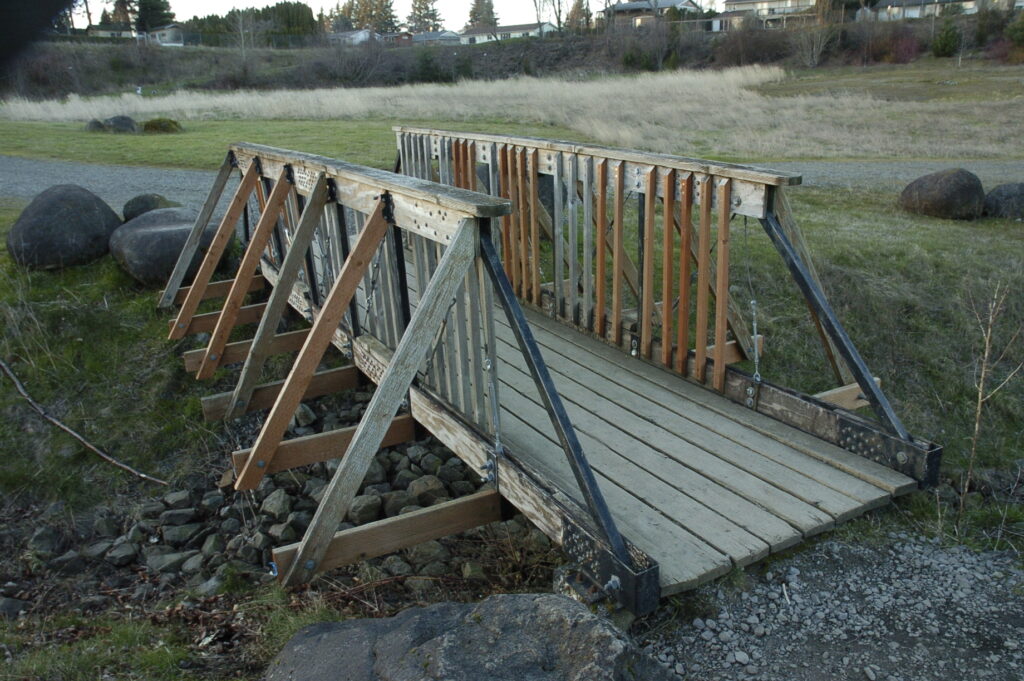
was built by a high school class.
This page will cover the different types of truss bridges, and how to use the Method of Joints and the Method of Sections to analyze the bridge.
What is a beam? A horizontal support. Here’s one
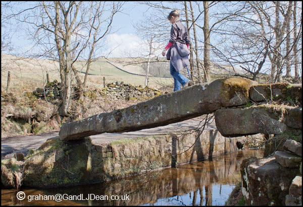
This beam bridge could easily support a couple hundred pounds.
How to turn a beam bridge into a truss.
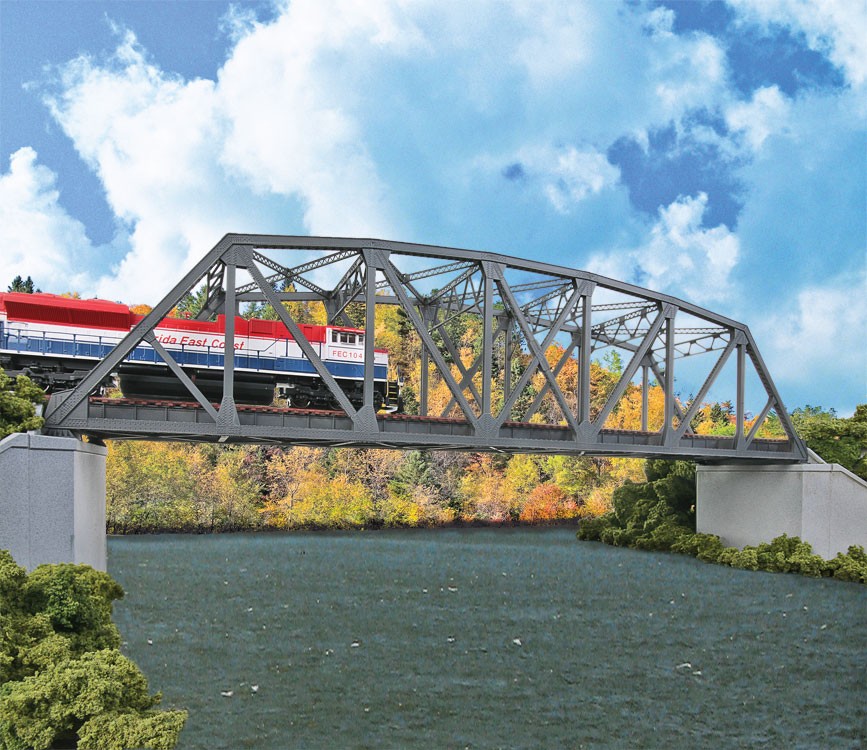
A truss bridge is made of 2-force members that carry the load in either Tension or Compression. Here’s a simple model to illustrate that.
A truss is a beam made of many smaller parts (members) some of which form triangles. Here’s a 5 pound truss model that easily supports a 150 pound load.
More video of the bridge made using 1/4″ plywood.
METHOD OF JOINTS- a handy tool for computing the forces in a truss
This 3 member (piece) truss is made of the 2 angled legs and the connecting member- the black thread connecting the legs at the bottom.
Before we can analyze the truss, we need to understand the 3 equilibrium equations.
Now to find the External forces acting on the truss.
First the reactions at A and C. We use the sum of the forces in the Y direction and the sum of the Moments about point A.
That means that when you use Sum forces in Y direction- the sum of the 2 reactions is not 11.9 but 9.4pounds. Next we use the Sum of the moments about point A-and use 9.4 instead of 11.9 pounds, and get 4.7pounds for the reaction @C and when substituting back into the earlier formula, we get 4.7 for the reaction @A.
Now for the Internal forces. We use the Free Body Diagram.
But the reaction @A is not 5.95 but 4.7 so when we substitute 4.7 into the equation for Sum vertical forces- Fab=negative 6.89 (not 8.72)
Finally we can compute the value of Fac-(the thread), which is what was the goal from the beginning.