TOWER CRANES
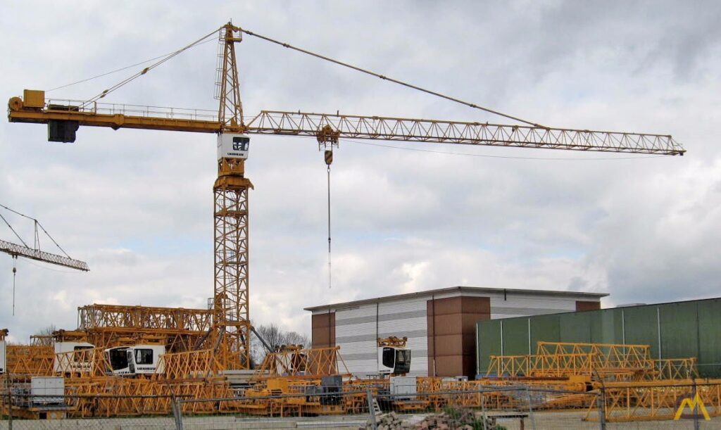
tower jib (boom) and counter-jib counter weight and pendants and here’s my first attempt.
The crane is built from 1×3 pine, lots of 1/4″ carriage bolts, a heavy duty swivel bracket and miscellaneous hardware.
We didn’t have a way to move the load along the length of the jib, so we hung the load from a dowel positioned closer in along the jib.
We need a trolley. Real tower cranes use a trolley to move the load along the length of the jib.
The pulley and turn-buckle set-up did not work well, so I made a new system using bike parts- chain and 2 sprockets.
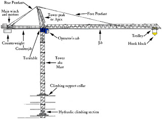
When the trolley moved in, the load automatically descended so I had to come up with an improvement to the tower crane trolley system. Billy Maguire (with Morrow Cranes in Salem OR) sent me a diagram showing how it’s done on a real crane.
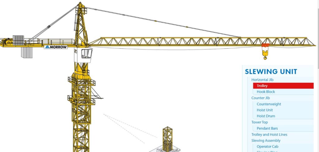
The trolley is controlled by a simple arrangement- there’s a line attached to the J hook mounted on 1 end of the trolley ( the black plywood). This line runs to the 2 sheaves (pulley wheel) mounted at the end of the jib-then back to the windlass ( I wrapped some sandpaper around the axle to prevent the line from slipping)- then on to the other j hook.
So much for the trolley. Now the load line-starts off tied to the eye bolt attached at the end of the jib- then runs through a small single sheave pulley screwed to the front of the trolley- then down to the lifting pulley, and up and through the 2nd single sheave pulley- finally through 3 more sheaves on its’ way to the windlass.
Now the 2 lines are separated and the trolley is not affected by the load line.