TRANSFORMER-
TEACHERS – are you looking for a curriculum that will get your students interested in engineering? Will the bridge deck crashing down do the trick?
I use this model of a cable stayed bridge to cover force vectors, torque, center of gravity, applied trig and overturning moment.
And as an added bonus, the kids can take the bridge apart and build:
a boom crane—a tower crane–a suspension bridge—an elevator—a cantilever bridge or anything they can dream up.
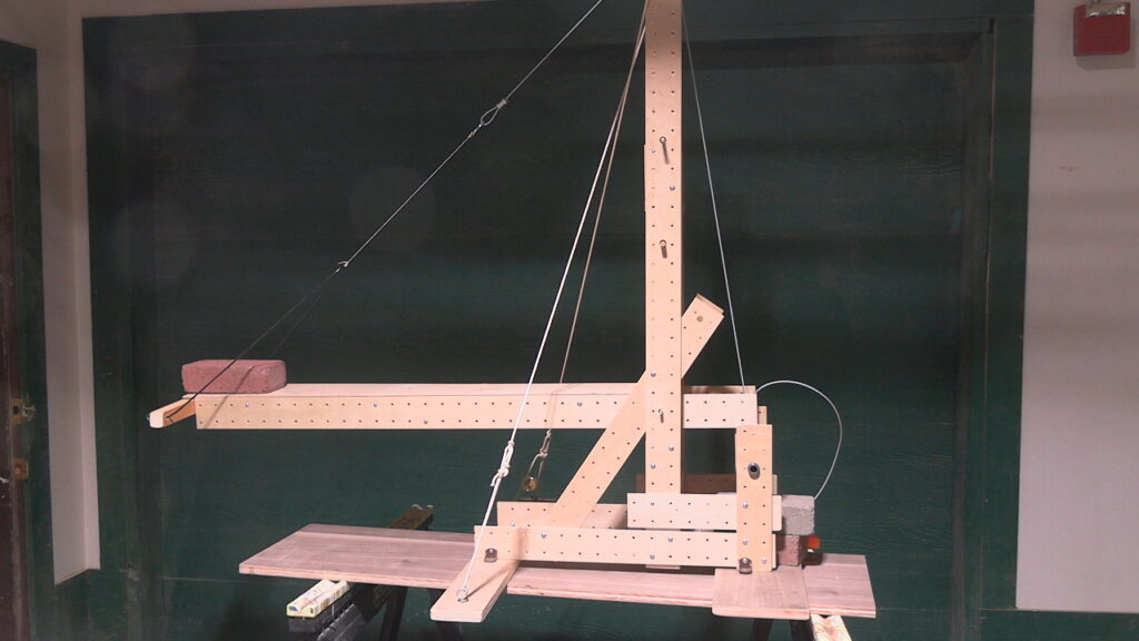
Changing the angle of the cable will change the Tension. How much tension will the cable support before it breaks?
There are lots of variables here.
size and placement of the load
angle of the supporting cable
thickness of the wood dowel.
In a cable-stayed bridge -with one or 2 towers- the cable stays that support then deck, extend from the tower directly to the deck
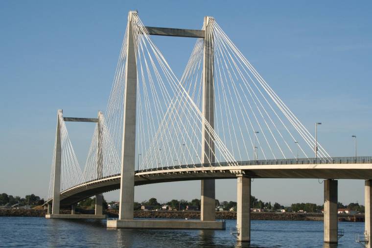
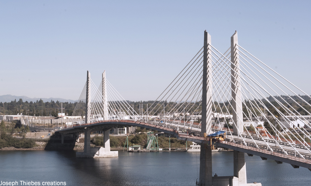

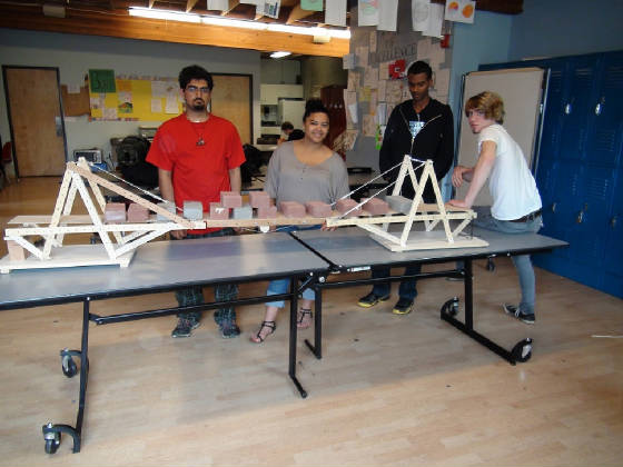
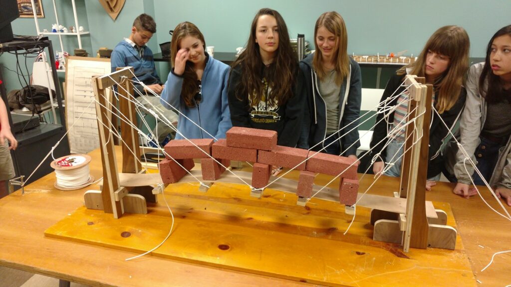
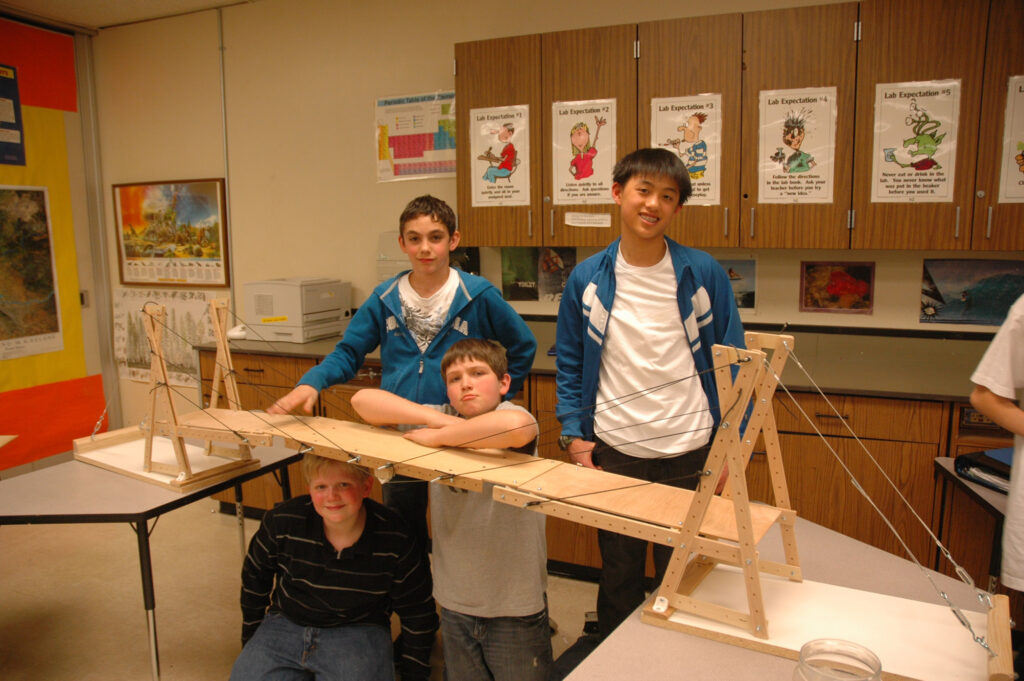
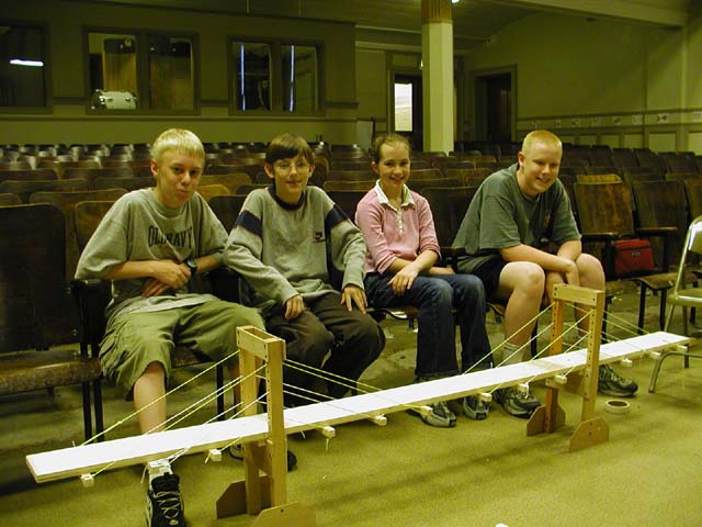
I’ve designed a curriculum that teaches the kids about force vectors, torque, center of gravity, applied trig and overturning moment. I use a model of a cable stayed bridge with just a single tower.
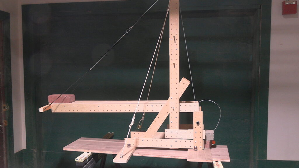
Now to the reason behind this new curriculum- how to compute the amount of Tension in the cable and figuring out when it will break and the deck will fall.
The 2×4 sits on the ground- or rather 1 end rests on the ground and the other end is held up by the string.
The 2×4 weighs 6#. One end rests on the ground (I use a small triangle to denote this) – so the ground is supporting half the 6# load.
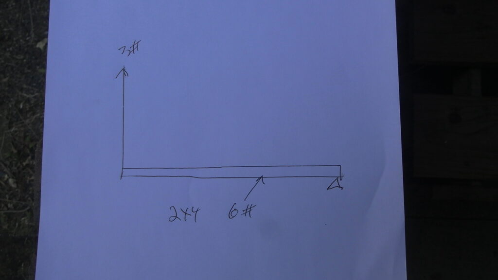
This means that Ben only needs 3# of force to lift the other end.
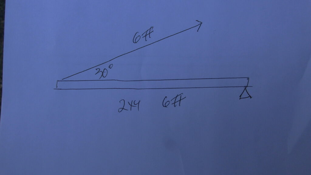
Now when Ben applies a force to lift the 2×4 at an angle of 30 deg. he needs 6# of force. We have to find a way to compute the force necessary at different angles.
Easy first we turn the forces into a right triangle.
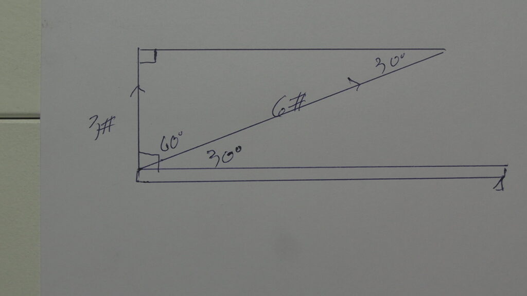
The vertical leg is 3#- that represents the original force when the lifting was vertical -90 deg.
The hypotenuse is the 6# force needed at 30 deg.
The complement to the 30 deg angle on the 2×4 is 60 deg. That makes the upper angle 30 deg.
The ratio of the opposite side ( the side opposite the angle we’re talking about- the 30 deg. angle)—3#
over the hypotenuse—-6# is 3/6 or 1/2 or .5
For those of you who don’t already know basic trig—this is SINE—– opposite divided by the hyp.
We write it like this— sin 30 = 3/6
sin 30 =.5
so substituting
.5 = 3/6
A triangle only has 3 sides and 3 angles so there are only so many ways to juggle the pieces-so how hard could it be?
Now we have the basic formula we can use to compute the tension in the cable at different angles.
What would the Tension(force) be if the string was at a 20 deg. angle?
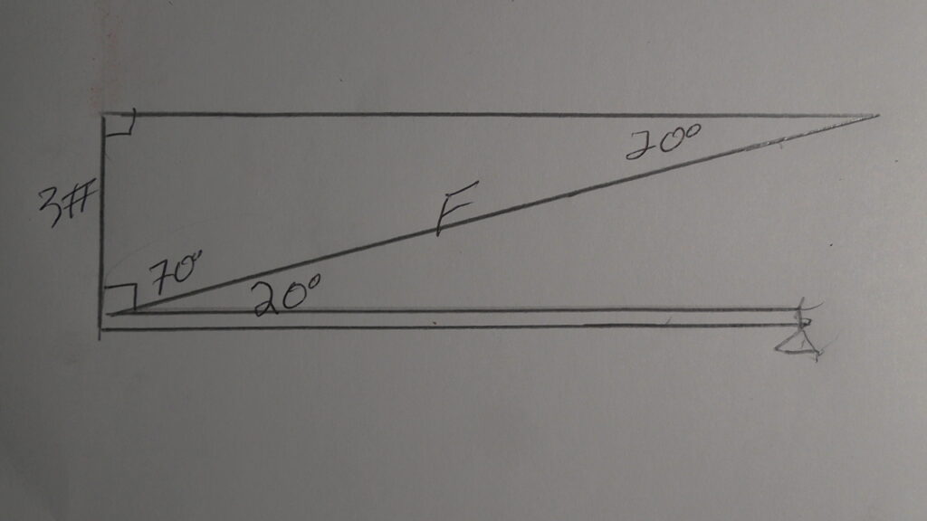
The vertical leg is still 3# and F is the unknown force required.
Sine will give us the answer.
sin 20 deg = 3#/F and sin 20 deg. = .342
now .342 = 3/F
substituting we get F= 8.77pounds of force
As we expected when we lowered the angle, the force (Tension) needed increased from 6# to 8.77#
I encourage my students to forget using their calculators to find the trig values. Instead use the trig tables like this one.
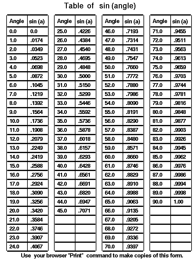
This way the kids can see how the sine values change as the angle changes.
All this was for the 2×4 but we need to use it for the cable of the bridge.
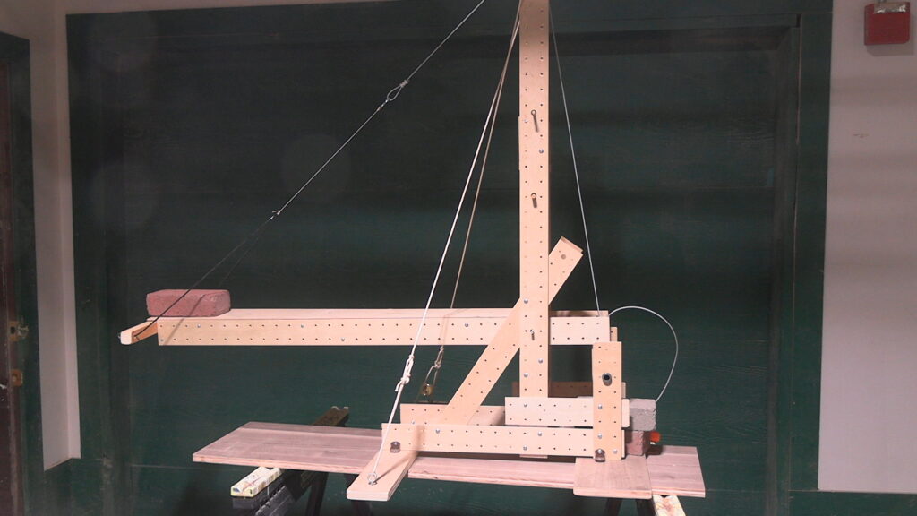
The deck of the bridge weighs 3.4#, and just as half of the weight of the 2×4 was supported by the floor, half of the deck (1.7#) is supported by the steel pivot pin mounted in the tower.
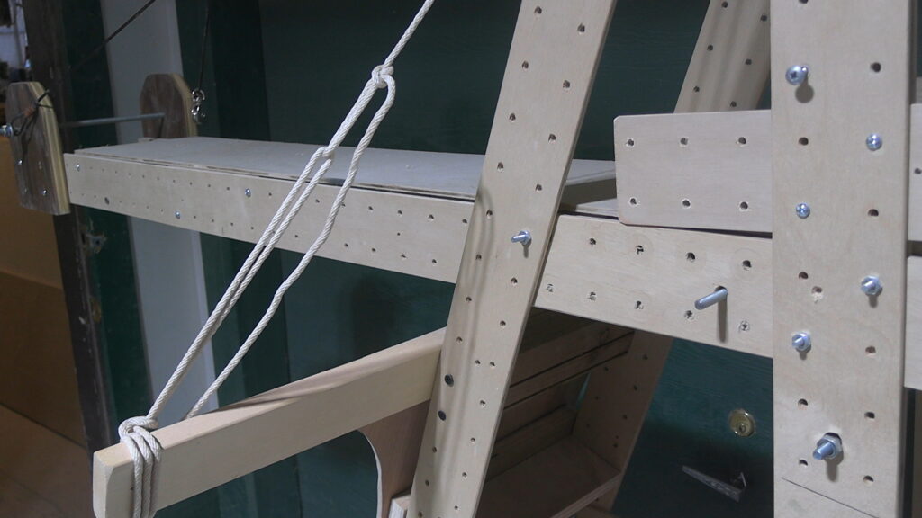
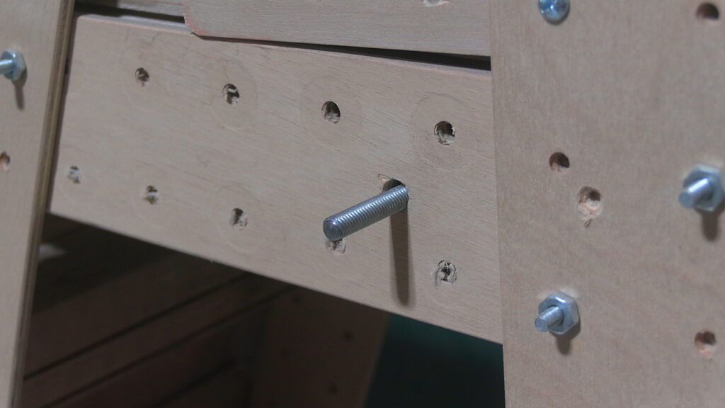
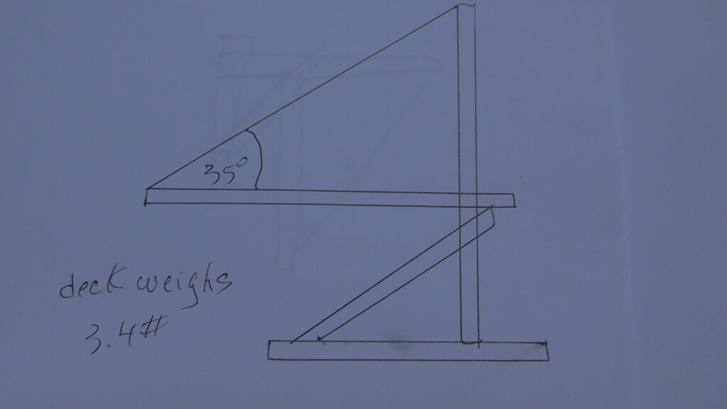
And the remaining 1.7# is the vertical leg of the triangle
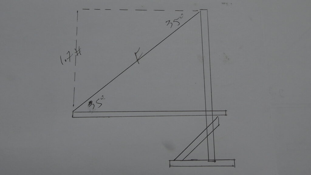
Here’s the formula:
sin 35 deg = 1.7/F
sine 35 = .573
with substituting we get
.573 = 1.7/F and finally
F = 2.9 pounds of force just to hold up the deck.
What is the Tension in the cable with a 2 brick load?
The entire 9.4# load is supported by the vertical leg of the triangle.
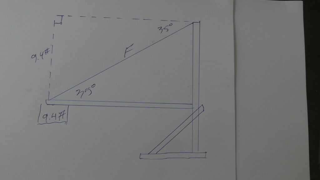
Here’s the set -up.
sin 35 = 9.4/F
sin 35 = .573
.573 = 9.4/F
F = 16.4#
Now we add the Tension in the cable from the weight of the deck (2.9#) and get
19.3#
Next we lower the cable to 15 deg.
First the Tension in the cable just for the deck. – Scroll up and review the formula
sin 15 = 1.7 /F
sin 15 = .258
.258 = 1.7/F
F = 6.58#
that’s just for the deck. Remember the Tension when the deck was at a 35 deg angle was 2.9#
Now the 4.7# brick
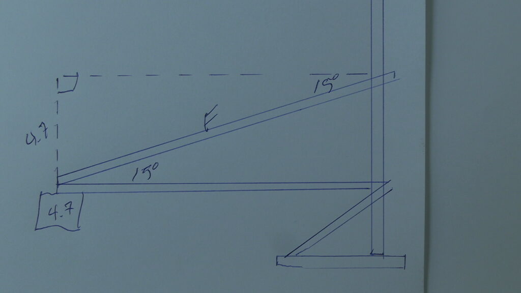
sin 15 = 4.7/F
sin 15 = .258
.258 = 4.7/F
F= 18.2# then we add the Tension from the deck (6.58#) and get
24.78#
much more than the 19.3# with 2 bricks @35deg.
That’s why the “cable” snapped and the deck fell.
I worked with a middle school team at Franciscan Montessori school. They managed to place 5 bricks
on the deck with a 35deg angle on the cable.
The deck was not level at the start but when the load increased, the deck leveled out and the angle approached 35 deg
Did you notice the windlass? The blue wheel has an axle connected to it. The line (string) wraps around the axle, so when the wheel turns, the line is gets pulled and the deck/load is raised.
Now the girls lowered the angle of the cable and added the bricks.
I introduced a new variable. I replaced the thin “strand” with a thicker line. Now the weakest link is the wood dowel, but when the
tension went from 9#s to 47#s, the dowel broke.
So the girls figured they needed a thicker dowel- a 1/2″ one instead of the 3/8″ one that broke. But the holes in the tower were drilled for the 3/8″ dowel and a 1/2″ wouldn’t fit and at the time I didn’t have a 1/2″ drill bit.
The girls came up with a simple yet elegant solution. They took 2 lengths of line (strong string) and put a loop at each end. The ends of the dowel were suspended by the 2 lines and the other ends of the lines (the loops) were hung from the threaded rod at the top of the tower. Look back at the video above- the line supporting the deck goes over the dowel and the down to an attachment. So the force in this line is pulling down on the dowel, but it’s being held up by the 2 looped lines-almost as good as if the dowel were being attached to the tower.
You can skip the 2nd half of the video
THE CABLE STAYED BRIDGE CAN BE TRANSFORMED INTO; –
-any number of cranes
-a cantilever bridge
-a suspension bridge
-a 2 tower cable stayed bridge
-a lift bridge
-an elevator
-anything you can dream up.
First a simple crane. The deck of the bridge now becomes the boom of the crane.
Now it’s time to “run the numbers” .
Torque is the force that causes rotation. The crane will rotate around the pivot point (fulcrum), if the torques aren’t equal.
So first find the torque of the load which tries to rotate the whole crane counter-clockwise (CCW).
Torque is measured in this case by inch pounds “/#.
W (Weight) in pounds (#) times D (distance) in inches (“)
W x D
The load weighs 7.2# and the crane body weighs-12#
The Torque of the load (I’m ignoring the torque of the boom for now) , so just the weight of the load 7.2#
W- 7.2# X D- 19.7″ = 141.8 “/# I used the cosine function to find the D
Now for the torque of the crane body. The crane weighs 12# and the center of gravity (CG) is 11″ from the
fulcrum- that’s the distance we want, so
W- 12# X D- 11″ = 132″/#
Now since the torque generated by the load is greater than the crane body torque, the crane tips over. Adding a 1 brick counter-weight was the solution.
Next I lowered the boom to 20 deg. and added 1 Brick (4.7#) as counter-weight. Would that be enough?
First the torque of the load and boom . Same load 7.2# but since the boom is lower, you can see that the load is farther away from the fulcrum. Since Torque = W x D ,if the D increases, then the Torque also increases.
Here are the numbers to prove that.
first torque of the crane body.. Same 12# but the CG (the point we measure the Dist. from) went from 11″ to 10″./
that’s because as the boom went down to 20 deg. a larger portion of the boom is now on the boom side of the fulcrum so the total CG moved 1″ towards the fulcrum.
So W x D = 12# x 10″ = 120’/#
Now the Torque of the brick ctwt.
W x D 4.7# x 20″ = 94″/#
combined Torque— – 214″/#
Now for the torque of the load and the boom.
W x D 7.2# x 26.36″ = 189.8″/#
I didn’t include the wt. of the boom when it was at a 40 deg angle because most of the boom was on the crane body side of the fulcrum, but you can see that more of the boom extends over into the “boom side” now.
The boom weighs 3# but only about 1.5# is on the boom side and the Dist is 20″ so
1.5# x 20″ = 30″/#
for a combined torque of 219.8″/#
219 is greater than 214 so the crane tips. All the measurements (weights, distances) are very rough, so the final numbers are also not exact.
That’s why we should use the FACTOR OF SAFETY. FS
In the real world all these measurements would be more reliable, but there are still variables to take into account. What if it’s a windy day and the load starts swinging? Then a “static” load (not moving) becomes a dynamic load and the torque on the load side increases.
A FS of 2 is recommended.
If the load generates a torque of say 100″/#, the the crane body should have a 200″/# torque.
So in this case, the 214″/# torque of the crane body should be increased to twice the load torque- 219.8 x2 = 439.6″/#
That means we need to add 225.6″/# of torque to the current 214″/# to get 439.6 “/# of torque.
What’s the easiest way ? Add more ctwt. at the far end of the crane.
How much ? The far end of the crane is 20″ from the fulcrum so that’s the D, and the needed extra weight is W
W x D (20″) = 225.6″/#
Divide by 20″ the ” cancel out and we get 11.38# 3 Bricks (4.7) will get us 14.1#
Here’s an example of the kind of problem you could give your students.
What’s the max. load you could lift with a boom angle of 30 deg., a ctwt. of 4 bricks (4.7) and a FS of 2?
First compute the torque of the crane- the weight is 12# . let’s say the CG is still 10″ which gives
12# x 10 ” = 120″/# the ctwt. (20″ is the Dist.)is 4 Bricks = 18.8# so 20″ x 18.8# = 376″/#
for a total torque of 496″/#
With a FS of 2, that means the torque of the load/boom must be half the 496 so 248″/#.
First we have to find the Dist. of the load.
The boom is 44″ long and the cos 30 deg. = .866 gives a Dist. of 24.5″
The load is X so W x D = X(24.5″) = 248 “/# which gives us
X= 10.1# which includes the load and the boom (to simplify I’ve neglected the torque of the boom)
Here’s a project for your students. A counter weight is what’s needed to prevent overturning. Let’s say you don’t have enough bricks or lag screws or ??? to use for counter-weight.
Remember Torque is Weight times Distance. To increase the torque on the crane body side, (and if you don’t have enough W) than use Distance.